
Relevant Judgment Method of Cable Fault Failure Point
1 Cable fault types and judgments We manufacture both sintered and electroplated bead wire. Sintered wire will provide better life while electroplated wire gives excellent cutting speed without lossing diameter. Whirlwind Wire is rubber cotated with spring spacers between the beads. Designed for slabbing marble boulders of calcareous limestone, dolomite. Diamond Grinding Wheel,Diamond Floor Grinding Wheel,Diamond Grinding Cup Wheel Premium,Diamond Cup Grinding Wheel Henan Huanghe Whirlwind International Co., Ltd. , https://www.huangheindustry.com
Whether it is a high-voltage cable or a low-voltage cable, faults often occur due to short-circuit, overload operation, insulation aging, or external force during construction, installation, and operation. The cable fault can be summarized as grounding, short circuit, and broken wire. The types of faults mainly include the following aspects:
1 three-core cable one or two core grounding.
2 Two-phase short circuit between cores.
3 Three-phase core wire is completely short-circuited.
4 One-phase core wire breakage or polyphase breakage.
For direct short-circuit or disconnection fault with a multimeter can be directly measured and judged, for non-direct short-circuit and ground fault, with megger to measure the insulation resistance between the core wire or insulation resistance between the core wire, according to its resistance value can be determined type of failure.
After the fault type is determined, finding fault points is not an easy task. Based on the author's experience, the following describes several methods for finding fault points for reference.
2 Finding Method of Cable Faults
(1) Sound measurement:
The so-called sound measurement method is based on the fault cable discharge sound to find, this method is more effective for the high-voltage cable core to insulation flashover discharge. The equipment used in this method is a DC voltage tester. The circuit connection is shown in Fig. 1, where SYB is a high voltage test transformer, C is a high voltage capacitor, ZL is a high voltage rectifier silicon stack, R is a current limiting resistor, Q is the discharge ball gap, and L is the cable core. Â 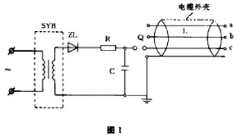 Â
Â
When the capacitor C is charged to a certain voltage value, the ball gap discharges the cable fault core wire, and at the fault, the cable core wire discharges the insulation layer to produce a “zig and sigma†spark discharge sound. If it is a buried cable, first determine and mark the direction of the cable. Then, when the noise noise is small, use an audiophile or medical stethoscope to search for it. When looking up, place the pickup close to the ground and slowly move along the direction of the cable. When you hear a loud “zizz,†discharge sound, it is the point of failure. Use this method must pay attention to safety, in the end of the test equipment and the end of the cable should be set up to monitor.
(2) Bridge method:
The bridge method uses the double-arm bridge to measure the DC resistance of the cable core, and then accurately measures the actual length of the cable. According to the proportional relationship between the length of the cable and the resistance, the fault point is calculated. In this method, the error for the direct short-circuit or short-circuit contact resistance between cable cores is less than 1Ω, and the error is generally not more than 3m. For faults with contact resistance greater than 1Ω at the fault point, the resistor can be reduced to 1Ω by increasing the voltage through burning. Below, measure again according to this method.  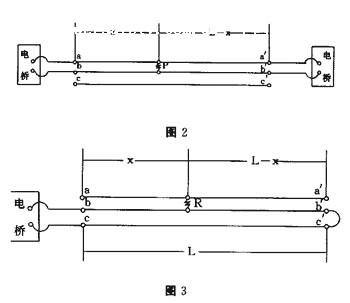 Â
Â
The measurement circuit is shown in Fig. 2. First, the resistance R1 between the cores a and b is measured. Then R1=2Rx+R, where Rx is the resistance value of phase a or b to the fault point, and R is the short contact point. The contact resistance. At the other end of the cable, the DC resistance value R2 between the a' and b' cores is measured. Then R2 = 2R(LX) + R, where R(LX) is the a' phase or the b' phase core is faulty. The resistance value of one phase of the point, after measuring R1 and R2, and then short-circuiting b′ and c′ according to the circuit shown in FIG. 3 , the DC resistance value between the two phases of the cores of b and c is measured, and then the resistance value is 1/2 is the resistance value of each phase of the core, denoted by RL, RL=Rx+R(L-X), from which the contact resistance value at the fault point can be found: R=R1+R2-2RL, therefore, fault The resistance value of the core on both sides can be expressed by the following formula: Rx = (R1-R)/2, R(LX) = (R2-R)/2. After the three values ​​of Rx, R(LX), and RL are determined, the distance X from the fault point to the end of the cable (X or LX) can be obtained by a proportional formula: X=(RX/RL)L, (L−X)= (R(LX)/RL)L, where L is the total length of the cable.
When the bridge method is adopted, the accuracy of measurement shall be ensured. The bridge connection line shall be as short as possible and the wire diameter shall be large enough. The connection with the cable core shall be crimped or welded. The decimal places shall be retained during the calculation.
(3) Capacitance amperometry:
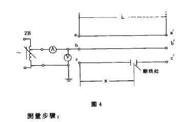
During the operation of the cable, capacitance exists between the cores and the core to the ground. The capacitance is evenly distributed. The capacitance is linearly proportional to the length of the cable. The capacitance current determination method is based on this principle. For cables Core wire breakage is very accurate. Measurement circuit shown in Figure 4, the use of equipment for 1 ~ 2kVA single-phase voltage regulator, 0 ~ 30V, 0.5 AC voltage meter, 0 ~ 100mA, 0.5 AC milliammeter a 0.5.
† Â
Â
Measurement steps:
1 First, measure the value of the capacitance current of each phase of the core wire (which should be equal to the applied voltage) Ia, Ib, and Ic at the leading end of the cable.
2 At the end of the cable, measure the values ​​of the capacitive currents Ia', Ib', and Ic' for each phase of the core to check the ratio of the capacitance of the perfect core to the broken core, and to determine the approximate distance of the disconnection.
3 According to the capacitance calculation formula C=1/2Ï€fU, C and I are proportional when voltage U and frequency f are constant. Since the f-frequency of the power frequency voltage does not change, the voltage to be applied must be constant during the measurement, and the ratio of the capacitance current is the ratio of the capacitance. Assuming that the full length of the cable is L and the distance of the broken line of the core is X, Ia/Ic=L/X, and X=(Ic/Ia)L.
During the measurement process, as long as the voltage is kept constant, the ammeter reading is accurate and the total length of the cable is measured accurately. The measurement error is relatively small.
(4) Zero potential method:
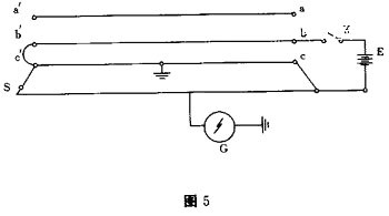
Zero potential method is the potential comparison method, it is adapted to the short length of the cable core to ground fault, this method is simple and accurate measurement, does not require precision instruments and complex calculations, the wiring shown in Figure 5, the measurement principle is as follows: Connect the faulty core of the cable in parallel with the equal length of the comparative conductor. When the voltage E is applied to both ends, it is equivalent to connecting the power supply at both ends of two parallel uniform resistance wires. At this time, any point on one resistance wire and the other The potential difference between corresponding points on the resistance wire is necessarily zero. Conversely, the two points where the potential difference is zero must be the corresponding point. Because the negative terminal of the microvoltmeter is grounded, and the point of failure of the cable is equipotential, therefore, when the positive terminal of the microvoltmeter moves to the point equal to the point of failure and equal to the indication point at the comparison lead, that is, the corresponding point of the fault point.
† Â
Â
In the figure, K is a single-phase knife switch, E is a 6V battery or 4 AA batteries, G is a DC microvoltmeter, and the measurement steps are as follows:
1 Connect the battery E to the core wires of phase b and c, and then lay a comparative wire S equal to the length of the faulty cable on the ground. The bare wire or bare aluminum wire should be used. The cross-section should be equal. There is an intermediate connector.
2 Connect the negative pole of the microvoltmeter to ground and the positive pole to a long soft wire. The other end of the wire requires full contact when sliding on the comparative wire.
3 Close the knife switch K and slide the end of the soft wire on the comparative wire. When the microvoltmeter indicates zero, it is the position of the cable fault point.