
The Application of Leader Huafu High-voltage Frequency Converter in Double Drive Hoisting Machine
Light Truck Spare Parts,Truck Spare Parts,Truck Spares, Light Truck Spares Jinane Baisheng International Trade Co.,Ltd , https://www.jnbisontruck.com
I. INTRODUCTION The mine hoist plays a very important role in the production of coal mines. It is a key equipment for mine production. Raising the technical performance of electric control devices not only directly affects the efficiency and safety of mine production, but also represents the overall level of mine hoist development. Therefore, it is required that the hoisting system of the mine hoist has the advantages of safety, reliability, efficient operation and accurate positioning.
In the traditional mine hoisting, about 80% is the use of AC winding motor rotor resistor series speed regulation, this speed control technology is relatively backward, invalid power consumption is too large, the structure is complex, and the operation is not ideal. In order to obtain a higher performance of the lifting system, part of the DC drive scheme is adopted. However, the structure of the DC motor is complicated. At the same time when the power range is subject to certain restrictions, the user also has a high maintenance cost during the operation. With the development of power electronics and motor control technology, the use of variable frequency speed control method has the characteristics of large torque, high precision, wide speed, and low maintenance, and fundamentally solves the drawbacks of other speed control methods. It is the current mine The preferred scheme of hoist electrical drive.
2. User Profile Huixian Longtian Coal Industry Co., Ltd. was established in April 2006. It is a modern joint-stock company controlled by Shenzhen Qianlong Industrial Group Co., Ltd. and has a mine with an annual output of 950,000 tons – Chengcun Mine. , The main production of No. 3 high-quality anthracite coal, the service period is 49 years, the mine was put into production in 2008, and the tax revenue is ranked in the top 10 in Xinxiang City. As shown in Figure 1 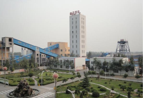
Third, the transformation of the background and program to determine the coal mine, vice wells hoist system in the construction of the well part of the design for the same two or different capacity of a motor work, a spare drag method, that is, a single drag method. With the increase of mine production capacity, it often happens that a single motor cannot meet production needs. If you re-purchase a motor with a larger capacity, the original motor will be eliminated, resulting in waste. At this time, you can consider changing the single-drag to double-driving without changing the device.
Longtian Coal Owner well was upgraded to a JKM-2.8/4(II) type multi-rope friction hoist equipped with a pair of 6T multi-rope buckets. The maximum input power of a single motor is 800KW, which has reached the maximum single-motor design standard. According to the design standards of the design institute, the maximum lifting capacity of the mine is 720,000 tons/year (a hook of 6T, 25 hooks/hour, 16 hours/day, and 300 days). Due to the heavy lifting of tasks, the main shaft upgrade has severely restricted the production of the mine. In order to improve this situation and improve production capacity, the main well is to be reconstructed. The 6T bucket is replaced with an 8T bucket. The single-motor drive is changed to dual-motor drive, and the electronic control system is transformed into AC-DC-AC high-voltage frequency conversion. Speed ​​hoist system, after the transformation, the production capacity has been increased to 950,000 tons/year (one hook, 8T, 25 hooks/hour, 16 hours/day, 300 days), the hoist has reached the maximum lifting capacity, and after the electric control transformation, the hoisting system is upgraded. The operation is more stable, it is easy to realize fully automated operation, effectively improving the safety of the system and reducing the labor intensity of the driver. At the same time, the high-voltage variable frequency speed control system has obvious energy-saving effect compared to the series resistance speed control system.
The preliminary scheme is designed to use two sets of high-voltage frequency conversion speed regulating devices to supply power to two motors respectively. Two high-voltage frequency conversion devices use vector control and master-slave synchronization to ensure the synchronous drag of the two motors and realize the same output torque of the two motors. The torque and power are evenly distributed, achieving smooth and pulseless operation within the entire speed range, and smooth running at low speeds. If one of the motors or inverters fails, the single motor can run at full speed and half load through external switching.
Fourth, the basic conditions of the basic parameters of the scene: Tower type multi-rope friction hoist, lifting height: 522m, tower height: 43.95m wire rope number: 4;
Lifting machine parameters: Model: JKM-2.8/4 (II), guide wheel diameter: 2.5m, main wheel diameter: 2.8m;
Reducer parameters: Model: ZHD2R-140, reduction ratio: 10.5;
Motor parameters: # 1 motor YR800-10, 800kW, 593rpm, 6000V, 98A, Shanghai Electric Group Shanghai Motor Factory Co., Ltd.; # 2 motor YR560-10, 800kW, 592rpm, 6000V, 103A, Jiamusi Motor Co., Ltd.;
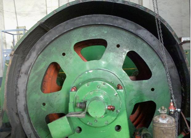
Inverter parameters: Model: HARSVERT-FVA06/120, rated voltage 6kV, rated current 120A, rated power 1000kW. The situation on the site is shown in Figure 2 and Figure 3. 
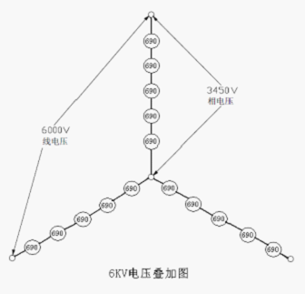
Fifth, the frequency changer system principle and the structure introduction This frequency conversion transformation selects 2 high pressure frequency changers which the model is HARVVERT-FVA06/120. HARSVERT-FVA series high-voltage frequency inverter is a new generation of energy feedback vector control high voltage variable frequency speed control system produced by Beijing Leader Huafu Electric Technology Co., Ltd. The system adopts four-quadrant series multi-level structure without network side reactor. The vector control algorithm is used to precisely control the motor. Due to the limitation of IGBT withstand voltage, the structure of 6kV high-voltage variable-frequency speed control system adopts power unit series mode. The 6kV series has 15 power units, and each 5 power units are connected in series to form a phase, as shown in FIG. 4 . The high-voltage frequency conversion system of our company adopts vector control. The high-voltage frequency conversion system is a double-closed-loop control system of speed and current. It has high voltage regulation precision and fast dynamic response.
HARSVERT-FVA series energy feedback vector control high-voltage inverter is composed of excitation surge suppression cabinet, transformer cabinet, power cabinet and control cabinet. The structure of each cabinet is shown in Figure 5. 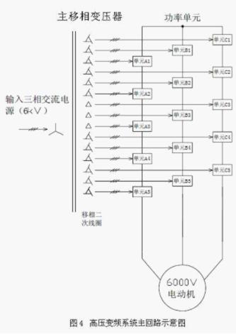
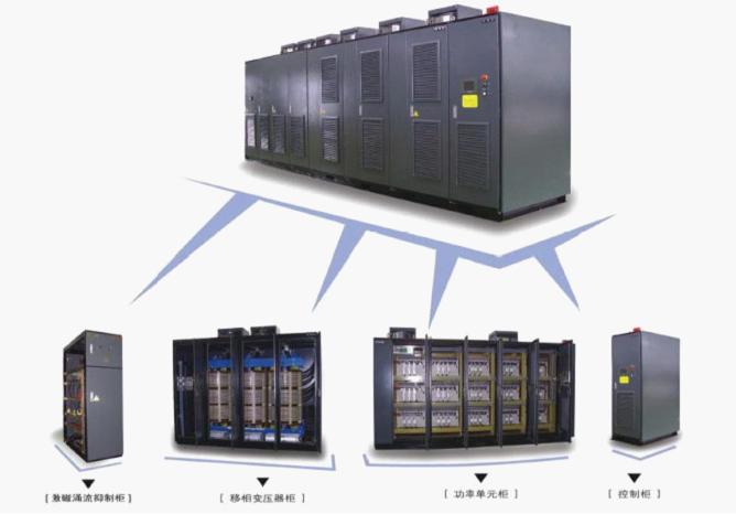
The following describes the structure and function of each component of the inverter one by one according to the order in which cabinets are placed from left to right.
When the inverter is powered on, the inrush current can reach 6-10 times of the rated current of the motor. The system is equipped with a vacuum contactor and a current limiting resistor in the excitation surge suppression cabinet, which can effectively limit the charging current and excitation when the inverter is powered on high voltage. Inrush current ensures that the inverter high-voltage power-on current is limited within 1 times of the rated current, and truly realize zero impact on the power grid. Specific function:
(1) Eliminating the impact on the IGBT during power-up, enhancing reliability and greatly increasing the service life of the equipment;
(2) Eliminating the impact on the power grid during power-on, avoiding the instantaneous drop of the grid voltage and interfering with the normal operation of other equipment.
The transformer cabinet is equipped with a rectifier transformer. The transformer adopts a maintenance-free dry-type transformer with an insulation class of H and a maximum withstand temperature of 180°C. The transformer transforms the high voltage on the grid side into multiple sets of secondary voltages on the secondary side to supply the power units in the power cabinet. Due to the independence of the secondary windings of the transformer, the main loop of each power unit is relatively independent, and its working voltage is determined by each low voltage winding. The output voltage determines that it is operating in a relatively low voltage state, similar to a conventional low-voltage converter, which facilitates the use of existing mature technologies. The relative voltage between each power unit is borne by the insulation of the transformer secondary winding, avoiding the problem of series voltage equalization. The transformer is equipped with a temperature control device that can monitor its internal temperature in real time, send an alarm signal when the temperature is high, and issue a trip signal when the temperature is too high. This transformer is compared with the general-purpose high voltage frequency changer's transformer, has two different, 1, because each module must return the energy to the electrical network, therefore the impedance requirement of each winding of the voltage transformer is more even, the cost is relatively high; 2, this transformer two The secondary winding does not need to be phase-shifted.
The power cabinet is equipped with power units. Each power unit has the same structure and is interchangeable. Its main circuit structure is shown in FIG. 6. The power unit uses IGBT for synchronous rectification. The synchronous rectifier controller detects the input voltage of the unit grid in real time. The phase of the input voltage of the power grid is controlled by the phase-locking control technology, and the phase difference between the phase and the grid voltage formed by the rectification inverter is controlled. Controls the flow of electrical power between the grid and the power unit. The phase of the inverter advances, and the power unit feeds back the power to the grid, whereas the power is injected into the power unit from the grid. 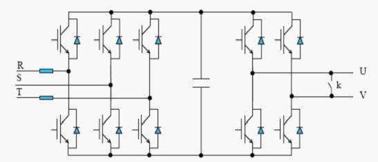
Through the front IGBT three-phase full-bridge mode rectification, charging the filter capacitor after rectification, determining the bus voltage, through the sinusoidal PWM control of the rear IGBT inverter bridge to achieve single-phase inverter. When the motor enters the power generation state, the diode in the rear IGBT finishes the freewheeling, and then full-wave rectification is performed so that the energy can be transferred to the filter capacitor. As a result, the bus voltage rises to a certain extent and the front IGBT is activated. SPWM inverter, through the input inductor, returns to the secondary pole of the phase-shifting transformer, and the energy is fed back to the power grid through the transformer. The product has the energy feedback capability of 100% rated power.
The output side of the inverter is connected in series by the U and V output terminals of each unit. The star connection is used to supply power to the motor. By reorganizing the PWM waveforms of each unit, the step PWM waveform shown in Figure 7 can be obtained. . This sine wave shape is good, dv/dt is small, can reduce the insulation damage to the cable and the motor, without output filter can make the output cable length longer, the motor does not require derating, can be directly used for the transformation of old equipment At the same time, the harmonic losses of the motor are greatly reduced and the resulting mechanical vibrations are eliminated. 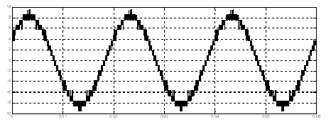
The control system is located in the control cabinet and consists of three parts: the main controller (DSP), the man-machine interface (embedded IPC), and the PLC. The three major parts have their own division of labor, and they communicate and work together. RS485 is used for data communication between human-machine interface, main controller and PLC. The communication protocol is Modbus protocol. I/O points and analog signal lines are used to establish simple communication between the host controller and the PLC.
High-performance AC drive systems all require closed-loop speed control, so Leader Huafu has developed high-performance vector control technology to ensure high accuracy and very accurate dynamic speed. The whole system uses a high-performance DSP microprocessor, which can automatically detect the parameters of the motor and establish a mathematical model of the motor. By detecting the voltage and current of the motor, the flux and torque of the motor can be decoupled in real time, and the motor can be controlled. The torque is actively limited to avoid overcurrent faults caused by load fluctuations.
The vector control product performance indicators are: speed range 100:1, steady-state speed accuracy 0.5%, dynamic torque response time is less than 200ms, starting torque 200% rated torque, basically reached the international advanced level. The use of DSP high-performance vector control of high-voltage variable frequency speed control system can achieve automatic tuning of motor parameters, real-time display and monitoring of system status variables and other functions.
Sixth, the transformation process and program adjustment After the installation of the inverter, first of all, the main circuit line transformation, and then the inverter control system and a single high-voltage debugging normal, synchronous installation of the console, connecting between the console and the inverter Connection, debugging console and inverter signal transmission, normal after the inverter and console access to the original system, with heavy load debugging is a key part of the transformation.
During no-load commissioning, the two devices used vector control with encoder and master-slave synchronization. It was found that the synchronization effect was not ideal, and there was a crash sound in the speed reducer during operation. It was not as stable as the VVVF control mode. Immediately tried to adopt the VVVF control mode and natural synchronization. It was found that the speeds of the two motors were slightly different at startup. There was a partial gap in the output current during the acceleration process, and the output current of the two motors was equivalent to the high speed stage. The mechanical operation of the entire process was good. Taking into account the difference between the two motor manufacturers, there are differences in current and speed parameters. Observing the single-station operation, the law of current variation of the two motors is also different. It is believed that the no-load meets the principle of torque and power distribution.
After running with load, the load from 6.5 to 10 tons was tested. It was found that the heavier the load, the better the balance of the two motors. After discussion with the user, it was decided not to use vector control, master-slave synchronization, VVVF control, natural Synchronous mode, this control method makes the two motors torque, power distribution, fully meet the operating conditions.
VII. Effect after transformation After the transformation, the frequency converter has been successfully applied to hoisting machine production and solved the various drawbacks of the original string resistance speed control system. The advantages are as follows:
(1) Eliminating the energy consumption caused by the rotor string resistance, it has a very obvious energy-saving effect;
(2) Overcoming the disadvantages of easily damaged contacts such as contactor and resistor winding motor brushes, reducing the incidence of failures and accidents, and improving the reliability of the system;
(3) soft start, large torque, stepless smooth speed control, rapid acceleration and deceleration. There is basically no mechanical impact during the start-up and acceleration/deceleration phases, which greatly extends the service life of the equipment.
(4) The degree of automation is high, the operation is simple, the main handle and the brake handle are not moved during the operation of the hoist, which reduces the driver's labor intensity and operation difficulty, and the operation is smooth without vibration and the noise is low;
(6) There is basically no maintenance workload, which reduces the workload of maintenance personnel;
(7) The system has more perfect hardware and software protection links.
VIII. Summary The high-voltage inverter speed control system has been operating for one year. Beijing Leader Huafu inverter was first run on a double-driving hoist and achieved a complete success, demonstrating the solid technical strength of Leader Huafu in the field of high-voltage transmission. The successful application of the HARSVERT-FVA series energy feedback high-voltage frequency converter in Longtian Coal Industry has greatly improved the safety and reliability of the main shaft hoisting system, ensured the high-quality operation of the main shaft hoist and created a huge Economic and social benefits. Practice has proved that the use of advanced technology, mature and safe high-voltage variable frequency speed control system can improve on-site conditions, improve the degree of system automation, and save energy. The use of high-voltage inverters can greatly reduce the amount of on-site maintenance, bring considerable benefits, and effectively respond to the country's call for energy conservation and consumption reduction, which is worth promoting.