Discussion on rationalization configuration of communication UPS power supply system
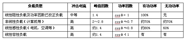
1 Introduction In today's communication networks, the trend of technology is the increasing integration of IT (information technology) and CT (communication technology). In order to ensure the reliability of power supply security, the Next Generation Communication Network (NGN) based on the core network technology based on softswitch technology will still use DC power as the basic power supply mode, but on the service support system platform. The AC power supply mode will also coexist. Based on a large number of applications of computer-based devices, UPS system devices are also increasingly used on communication networks. The power supply object has been developed from a single computer device to a service terminal, a network server, a network device, a data storage device, a service support platform, and even an entire communication network. The scope of power supply objects mainly involves computer terminals, servers, routers, switches, displays, disk storage arrays, minicomputers, and the like. The way the power is supplied has also evolved from a small UPS decentralized power supply to a centralized power supply to a large UPS. In order to ensure the reliability of power supply, even n+1 parallel hot backup system or even dual bus UPS system power supply mode is adopted. A well-designed UPS power supply system can provide high-quality power to the load. However, in practical applications, many problems are often caused by the UPS power supply system. Therefore, how to establish a reasonable and safe UPS power supply system has become a concern of everyone. This article will discuss this issue from the perspective of UPS power supply system design. 2 UPS system capacity configuration The load capacity of the UPS is the first consideration for the user when selecting the UPS. That is, how much UPS is needed, and the ability of the selected UPS to carry the load under various conditions needs to be taken seriously. The UPS is not like a transformer. As long as the load power does not exceed its rated output capacity (kVA), no matter what the load is, the output capacity of the UPS is not only related to the load but also to the nature of the load. Reasonable configuration of system capacity not only ensures the power quality of the UPS, reduces the failure rate, but also saves investment and improves economic efficiency. 2.1 Select system capacity according to load size in UPS Care must be taken when selecting the type. It is not for the high reliability of the UPS operation. One-sidedly, the greater the capacity of the UPS, the higher the reliability. If the UPS is running at light load for a long time, it will help reduce the probability of damage to the inverter, but it increases the possibility of battery failure inside the UPS. Because the discharge current of the battery is too small and the discharge time is too long, it is easy to cause deep discharge and permanent damage. If the UPS is in heavy-duty operation for a long time, this will save a part of the investment, but because the inverter is in heavy-duty operation, its output waveform will be distorted and the output voltage amplitude will be too large. This will not provide a high-quality power supply for the load, and it will easily cause damage to the drive components of the UPS inverter. Therefore, even from an economic point of view, it is not worth the loss. According to the current recommendation of some UPS manufacturers, the UPS single unit is configured according to the load capacity of 60% to 80%, and the parallel machine is configured to be 35% to 40% per load. In addition, when the UPS is selected, the capacity expansion of the load system should also be considered. The pre-added load capacity is about 20%. For the case where the communication equipment room is large and the load is continuously expanded in stages, when the UPS capacity is configured in the first phase, the medium and long-term development trend should be properly considered, and the models that can be operated in parallel or multi-machine are selected in the selection to make When the medium and long-term load capacity increases, the output capacity is expanded by the UPS. Correspondingly, when configuring the UPS input and output power distribution screen, you should reserve multiple UPS input switches and medium and long-term load shunt switches for future expansion. For example, if the actual load of the UPS is 60kVA, the minimum selected capacity of the UPS can be estimated as: (60kVA + 60kVA × 20%) / 60% = 120kVA. 2.2 Select system capacity according to load characteristics Load properties are generally classified into linear loads (including resistive loads or power factor corrected loads, inductive loads, capacitive loads) and non-linear loads (ie, rectified and filtered loads with electrolytic capacitors). According to the above table, different power loads have different power factor and crest factor, so the choice of UPS must consider the nature of the load. The input power factor of most computer equipment is micro-capacity 0.7, and the load that UPS mainly targets is these intelligent precision equipment. For this reason, all UPS designs need to adopt parameters with output power factor matching of 0.7-0.8. Thereby maximizing the load capacity of the UPS. In the case of power factor matching, that is, the input power factor of the computer load is micro-capacity 0.7, and the output power factor of the UPS calibration is also 0.7, the ratio of the VA of the load to the VA of the UPS is 1:1. That is to say, a UPS with a capacity of 1VA can carry such a load of 1VA without considering the factors such as impact and capacity. If the power factor does not match, such as a resistive load, a 1VA capacity UPS can only have a 0.7VA resistive load, otherwise the UPS will be overloaded (even if the UPS VA number is greater than the VA number at the load). Selecting the load capacity should also consider the inrush current of different loads. Usually, the UPS has a crest factor of 3:1, which is suitable for the crest factor requirement of non-linear load such as computer in normal operation. However, when the impact is large, the current capacity of the power supply equipment such as the UPS multiplied by 3 is not enough to meet the instantaneous current requirement of the load. In this case, it is necessary to consider increasing the capacity of the power supply device, thereby improving the current supply capability. Usually, the computer load generates a large inrush current that is more than twice as large when it is turned on. Usually exceeds the UPS's crest factor providing capability. Therefore, when selecting the UPS capacity, it is necessary to consider the load fluctuation and the impact margin, and appropriately increase the UPS capacity to resist the fluctuation of the load. Select the UPS capacity margin as: UPS capacity (VA number): Computer Load capacity (VA number) = 1:0.7 For some special loads, a strong inrush current is generated during starting or working, and the load capacity is instantaneously increased several times (sometimes up to 6 times). For this type of load, the margin should be further increased based on the ratio of the normal capacity margin. The correct capacity ratio has a great impact on the normal and stable operation of the UPS and the working life of the UPS. The chance of a UPS system failure that often works under full load or overload conditions is much higher than that of a UPS with the correct capacity ratio. 3 UPS battery capacity configuration Reasonable selection of the capacity of the battery is an important guarantee for the UPS to supply power to the load device. If the capacity configuration is too large, the battery cannot be fully utilized, and resources are wasted; the capacity configuration is too small, and the user's requirement for backup time cannot be satisfied, and the battery life is unfavorable. Battery capacity selection should follow the following principle: the battery must be supplied to the inverter during the backup time, and under rated load, the battery voltage should not fall below the minimum voltage allowed by the inverter. The backup time should be greater than the time from the interruption of the mains to the recovery or the time required for the normal power supply of the generator set (the front-end power supply system is equipped with a generator set). If this period is long, an external long-delay battery should be configured. Group, but at this time should confirm that the UPS internal rectifier has the ability to externally connect the large-capacity battery pack for charging, otherwise an external charger should be configured. Now the communication bureau (station) requires the start-up time of the oil machine after the power failure to be 15 minutes, and the actual load carried by the parallel redundant power supply in the UPS operation is about 60%, so it is recommended that each medium and large UPS be backed up. The battery delay time (calculated according to the UPS with full load) is generally 1 hour. There are many calculation methods for the capacity of UPS backup batteries. Constant power method (table lookup method), estimation method, power supply method, constant current method, etc., different calculation methods have different results, it is difficult to say which calculation method is the most accurate. Various calculation methods have their own emphasis. In practical applications, it is necessary to comprehensively consider the use of the battery, the load conditions of the UPS and the application occasions to select a suitable battery capacity calculation method. Among them, the constant current method is relatively simple and suitable for the calculation of all brands of batteries, which is a rough battery configuration method. Constant flow method calculation formula: C = (P × T) / (V × η × K), Among them: C--battery capacity (AH), P--load power (W), T--ideual spare hours (h), V--UPS battery pack rated voltage (V), η--battery inverter efficiency (Check the table), K--battery discharge coefficient (check the table) For example: Emerson series 120KVA UPS backup time 1h, select Huari 2V series battery. Estimate battery capacity. Solution: UPS general power factor is 0.8, P=PUPS×0.8=120000×0.8=96000(W), V=192×2=384(V), look up table η=0.9, K=0.3 C=(P×T)/(V×η×K)=(96000×1)/(384×0.9×0.3)=926(AH) That is, 2V500AH battery 2 group is selected, which can be used. 4 Parallel redundant operation mode selection In the communication station (station), the communication equipment is not allowed to be powered off. In order to improve the reliability of the UPS system, facilitate the expansion of the UPS system, and regular maintenance, the parallel operation mode is often adopted. There are a variety of redundant connection methods, each with its own advantages and disadvantages. When considering the solution, choose the appropriate mode according to the actual load situation. The current parallel redundancy operation can be roughly divided into two categories: (1) Hot backup (ie, serial redundancy). The UPS has a master and slave. The basic principle is that the load current is 100% when the host is normal, and the backup power is provided by the slave when the fault occurs. Since the standby UPS is waiting for a working state at the host bypass, it is called a hot backup. The structure and control of the system are simple, but the following disadvantages exist: the host works for a long time, and the slave is in a long-term standby state, the components of the two machines are not aging, and the battery of the slave is in a floating state for a long time, which affects the battery life; In the state where the slave is powered, the host may bypass the power supply and cause a bottleneck fault. The system load cannot exceed the capacity of the single unit and cannot be expanded later. (2) Parallel redundancy. More than two UPSs of the same model and the same power are passed through the cabinet, the parallel module or the parallel board, and the output ends are connected in parallel. The purpose is to share the load power. The basic principle is: under normal circumstances, both UPSs are output by the inverter to divide the load and current. When one UPS fails, the remaining UPS bears the full load. Three-machine parallel connection is also a common method. For example, for a 60KVA load, we can consider three 30KVA parallel connections. Even if one UPS fails, the other two UPS can still bear the full load. This is N+1 parallel redundancy. The essence of parallel redundancy is that the UPS divides the load. In this way, there are usually two kinds of structures. One is that the UPS is connected in parallel and the cabinet is connected in parallel, and the cabinet provides synchronization and multi-machine current sharing control, and provides the total static bypass of the parallel system. The other is in each UPS. A logic control board is installed inside to control the synchronization and current sharing output of each machine. The advantage of this solution is that it is easy to expand (the cabinet should be considered in the final stage when using the cabinet mode), and the reliability of power supply can be improved through redundant backup. However, there are also some shortcomings: the use of the cabinet and the cabinet will generally become the common bottleneck of the system. Once the internal control or failure occurs, the entire system will fail to supply power. In addition, it is difficult to maintain the same UPS output parameters. It will also cause each UPS to supply power to the load and also form a circulating current between the inverters inside the UPS. When the circulating current is too large, the safety of the inverter will be directly jeopardized; if the current difference between the UPS and the load is too large, it will make The aging speed of the power amplifying component of the inverter is unbalanced, which may also cause a fault. Generally speaking, the more the number of parallel devices in the power supply system, the greater the probability that the UPS power system will malfunction. 5 UPS input power distribution options The UPS can provide a high-quality power supply with high voltage regulation, stable frequency, and small waveform distortion to the load, and can provide power supply without interruption when switching with static bypass. But to do this, the quality of its pre-stage power supply cannot be ignored. When designing the front-end power supply system of the communication equipment room, we should consider the following aspects: (1) The power quality of the power supply system of the front stage should not be too bad, and the voltage and frequency should be stable within the normal range. At present, the range of UPS designed with thyristor is -15%, +10%, the range of design with IGBT rectifier is -25%, +23%; the range of frequency is best to choose a wide range of 50Hz ± 5Hz; the voltage is too low, The UPS backup battery will be frequently discharged, and the service life will be greatly shortened due to the long-term undervoltage charging state. On the contrary, if the voltage is too high, the inverter may be damaged. For the bypass input, the voltage and frequency fluctuations also have a certain range, generally ±10% of the rated voltage. If the range of the front-end power supply is too large, the switching between the inverter and the bypass power supply is prohibited or Intermittent. Therefore, if the front-end power grid of the communication equipment room does not meet the voltage range, a suitable anti-interference AC power supply should be configured in the front stage of the UPS, but it is not appropriate to use a tube-type AC voltage regulator or a magnetic saturation regulator because These two types of regulators can generate instantaneous high voltage when starting up, and the output waveform distortion is also large, which is easy to cause UPS failure. (2) The front-end power supply system should not carry other frequent starting loads, such as elevators that are frequently used, air conditioners that are frequently turned on, etc. The reason is that when these loads are turned on and off, there will be instantaneous high and low voltages, which will make the voltage waveform distortion on the power supply line too large, causing the UPS mains bypass power supply and the inverter power supply switching control circuit to malfunction, which will cause the synchronous control circuit to malfunction. . Therefore, under the condition of permission, the UPS power supply should be placed at the front end of the grid input. (3) The capacity of the alternator in the pre-stage power supply system should be properly amplified. Most communication equipment rooms are equipped with generator sets to solve the problem of power supply failure for a long time. However, when configuring the generator set, its capacity should be considered not less than 1.5-2 times of the rated output power of the UPS power supply to ensure that the generator output voltage and frequency are normal, and the waveform distortion is improved. (4) UPS main input and automatic bypass input should be used for isolation requirements. If both inputs are introduced by the same AC power distribution panel and the internal processing of the machine is connected, there will be a serious "single point of failure" hazard. When the device is internally short-circuited, a serious overload occurs, causing the main input to open and trip. The automatic bypass that shares the same open will fail at the same time, causing a load disconnection accident. The UPS internal rectification input and the automatic bypass input jumper should be removed, so that the UPS can be changed from single input to dual input, that is, the UPS's power transmission route is changed to two-way, and the two UPS are rectified to the UPS. And automatic bypass power transmission, so as to avoid the problem that the UPS can not turn bypass after the rectifier input switch fault trips. 6 UPS wiring selection It is very important to choose the wiring reasonably. The wiring wire diameter is too thin, the current is too large, and it is easy to generate heat and cause fire. If the wire diameter is too thick, it will cause waste. The AC power line can be selected according to the economic current density method, and the economic current density method is calculated as: S=Im/Ji. Where S is the copper wire diameter (mm2), Im is the maximum load current (A), and Ji is the economic current density (2 to 4 A/mm2, generally 2.25). For example, if a communication station has a maximum load current of 100A, then S=100/2.25=44.44 (mm2), so it is best to use a 50mm2 copper cable. For the UPS power system, the cross-sectional area of ​​the neutral line should be 1.5 to 1.7 times the cross-sectional area of ​​the phase line cable; for the UPS power system, the cross-sectional area of ​​the ground line should be 0.5 to 1 times the cross-sectional area of ​​the phase line, but not less than 6 mm2. The DC cable (battery cable) can be selected according to the current moment method. The current moment method is calculated as: S = (I × L) / (K × ΔV). Where S is the power cable diameter (mm2), I is the power line load current (A), L is the power line loop length (in m), K is the power line conductivity (m / Ω ​​× mm2), copper wire is 57, ΔV is the voltage drop across the wire, generally 2.6V. For example, the maximum load current of a communication station is 100A, the length of the battery line is 20m (the length of the 20m battery line includes the round-trip line), and the fixed voltage drop is 0.5V. The required battery line is S=(100×20). / (57 × 0.5) = 70.2 (mm2), a 75mm2 copper cable should be used. 7 Conclusion The quality of a UPS power supply solution directly determines whether the important load in the communication equipment room can operate normally. When configuring the communication room UPS power supply system, we must save investment, consider the reliability and flexibility of the system, and provide effective protection for communication equipment and computer load. Rubber Conveyor Belting,China Conveyor Belt,Types of Conveyor Belts,EP Conveyor Belt Vibrating Screen ,Fence Type Co., Ltd. , http://www.nbweldedmesh.com