Reciprocating vacuum pump maintenance and repair methods

â‘  parts quality standards and maintenance

a. There should be no cracks on the inner surface of the cylinder cylinder, trachoma, scars, grooves and other defects, the maximum surface roughness of the valve slide vacuum pump Ra 1.6μm. Measuring cylinder roundness, cylindricity deviation, according to the degree of wear and tear to determine boring cylinder or replacement. Under normal circumstances, the cylinder deviation of circularity and cylindricity shall comply with the provisions of Table 4-8.
Boring cylinder, the cylinder diameter increases shall not exceed 2% of the original size, cylinder wall thickness reduction of not more than 1/12 of the original wall thickness.
Table 4-8 reciprocating vacuum pump cylinder maximum allowable cylinder bore tolerance and tolerance / mm

Cylinder diameter
Maximum wear
Boring cylinder allows
deviation
Cylinder diameter
Maximum wear
Boring cylinder allows
deviation
Roundness tolerance
Cylindrical tolerance
Roundness tolerance
Cylindrical tolerance
> 200 ~ 250
> 250 ~ 300
> 300 ~ 35Q
0.40
0.45
0.50
0.25
0.30
0.35
± 0.04
± 0.05
± 0.05
> 350 ~ 400
> 400 ~ 450
> 450 ~ 500
0.55
0.60
0.65
0.40
0.45
0.50
± 0.06
Soil 0.06
± 0.07
b.SZB-type cantilever water ring vacuum pump crankshaft, connecting rod and bearing on the crankshaft non-destructive testing or magnifying examination and found to have cracks, you should replace the crankshaft. Crankshaft neck and crank neck abrasions, dent area shall not be greater than 2% of the journal area, trench depth shall not exceed 0.10mm, otherwise, should be carried out grinding repair. Crankshaft journal grinding, the maximum reduction of not more than 3% of the original diameter. Crankshaft main journal and crank neck wear, should not exceed the value specified in Table 4-9, if the wear is more uniform, can be repaired by metal spraying method.
Link rod corrector can be used to check or correct the bending or torsional deformation of the connecting rod, which still can not meet the quality standards after correction that should be replaced. The straightness of the connecting rod center and the small head pin hole center line to the end face shall not exceed 0.0 5 mm.
Table 4-9 reciprocating vacuum crankshaft maximum allowable wear / mm

Journal diameter
Maximum allowable wear value
Main journal
Crank neck
Roundness tolerance
Cylindrical tolerance
Roundness tolerance
Cylindrical tolerance
≤80
81 ~ 1 80
181 ~ 270
0.05
0.06
0.08
0.04
0.05
0.08
0.05
0.06
0.08
0.04
0.05
0.08
SKA direct water ring vacuum pump bearings bearing alloy should be good with the tile shell, solid, without cracks, pores, delamination and other defects. Bearing bush bearing contact area and the back of the contact area of ​​not less than 40% ~ 50%, between the two may not place the gasket. Bearing bushings and journal should be uniformly contact point, the contact angle should be 60 ° ~ 90 °, the contact point of not less than 2 to 3 per square centimeter. Bearing bush and journal radial clearance (1% 0 ~ 2 ‰) D (D is journal diameter).
c. Piston, piston ring piston and piston ring surface should be smooth, no cracks, trachoma, scars and other defects. Piston and cylinder installation clearance and the relative allowable wear value in Table 4-10 provisions.
Table 4-10 Piston and cylinder installation clearance and wear allowable value / mm
Cylinder diameter
First safety
Install the gap
Maximum allowable wear value
Cylinder diameter
First safety
Install the gap
Maximum allowable wear value
gap
Roundness
Cylindricity
gap
Roundness
Cylindricity
200 ~ 250
250 ~ 300
300 ~ 350
0.23
0.27
0.33
2.00
2.40
2.80
0.50
0.60
0.60
0.50
0.60
0.60
350 ~ 400
400 ~ 450
450 ~ 500
0.38
0.43
0.48
3.4
3.90
4.50
0.70
0.70
0.80
0.70
0.70
0.80
Piston ring should have sufficient elasticity, and cylinder wall contact surface length of not less than 60% of the circumference. Piston ring in the ring groove
When installed, its openings should be offset from each other 120 ° ~ 180 °. Piston ring openings in the cylinder clearance, backlash in the groove and the maximum allowable wear value in Table 4-11.
Table 4-11 Piston Ring Installation Clearances and Allowable Maximum Wear / mm

Cylinder diameter
Install the gap
Allow maximum wear
Cylinder diameter
Install the gap
Allow maximum wear
Open
Backlash
Open
Backlash
Open
Backlash
Open
Backlash
200 ~ 250
251 ~ 300
301 ~ 350
1.00
1.20
1.40
0.05 ~ 0.07
0.06 ~ 0.09
0.06 ~ 0.09
4.00
4.50
5.00
0.20
0.20
0.20
351 ~ 400
401 ~ 450
451 ~ 500
1.60
1.80
2.00
0.07 ~ 0.10
0.07 ~ 0.10
0.09 ~ 0.12
5.50
6.00
6.50
0.20
0.20
0.20
d. Piston rod The straightness of the piston rod is 0.1 0 mm. The maximum wear value of the piston rod shall not exceed (0.05 ~ 0.07) D (D is the piston rod diameter).
e. Valve plate and seat The valve plate and valve seat with no pitting, scratches and other defects. Valve and valve seat should be in close contact with the kerosene test within 5 min without continuous leakage. Spring should have sufficient elasticity, the same valve spring free height should be the same.
f. crosshead and rail crosshead should be free from cracks and other defects, crosshead and pin maximum wear should be less than 0.50 mm, crosshead pin and bushing clearance of 0.03 ~ 0.06 mm. Check the crosshead and the rail contact with the coating method, the contact area of ​​not less than 60%, the contact point evenly distributed, when not up to the requirements should be ground. Check the gap between the crosshead and the guide rail with a feeler gauge and the value is to comply with Table 4-12.
Table 4-12 Cross head and rail mounting clearance / mm

Crosshead diameter
Install the gap
80 ~ 120
121 ~ 180
181 ~ 260
0.20 ~ 0.24
0.24 ~ 0.29
0.29 ~ 0.34
(2) When adjusting and adjusting, the clearance between the piston before and after the dead point and the cylinder head should be 1.50 ~ 2.00 mm. The valve adjustment method is: a. Crankshaft cranks just beyond the top dead center; b eccentric position at the highest point on the plumb line; c. Valve placed in the center of the valve seat; d The entire valve actuator in the above position fixed.
â‘¢ test and acceptance
a. Water ring vacuum pump before the test preparation
(a) Lubricating grease and grease are added as required in each lubrication point and crankcase.
(b) Check the auxiliary equipment, pipeline valves and instrumentation is installed properly.
(c) Check whether the fasteners of each department are fastened and the safety guards are firm and reliable.
(d) Check if the cooling water is clear.
(e) There is no abnormal phenomenon of turning the car.
(f) Open vent valve and vent valve and close suction valve.
b. Test procedures
(a). Instantly start the motor, check the direction of operation, confirm the correct and then restart.
(b) Close the vent valve, listen to the cylinder and crankcase with or without any abnormal sound, check the ammeter, vacuum gauge indicates the normal.
(c) Check that the cooling and lubrication system is working properly.
(d) Check if the vacuum meets the production requirements.
(e) Check the ministries temperature: cooling water outlet temperature does not exceed 35 ℃; eccentric wheel temperature does not exceed 50 ℃; valve temperature does not exceed 90 ℃; rolling bearings and plain bearings temperature not exceeding 75 ℃ and 65 ℃.
Maintenance quality to meet the requirements, maintenance records complete and accurate, load operation 2 ~ 4h after the operation of all ministries under normal operation, technical performance is good, to reach the nameplate rated capacity or capacity to identify, according to the provisions of the acceptance procedures, handed over to production.
â‘£ common pump failure and troubleshooting Reciprocating vacuum pump troubleshooting and troubleshooting are shown in Table 4-13. In case of any of the following circumstances should be immediately stopped.
a. Abnormal vibration and noise appear.
b. Chemical pump ammeter current exceeds the rated value, continuous non-drop.
c. When liquid material enters the pump body or there is danger of entering the pump body.
d. cooling water cut off.
Table 4-13 Reciprocating Vacuum Pump Common Malfunctions and Remedies

Cylinder diameter
Maximum wear
Boring cylinder allows
deviation
Cylinder diameter
Maximum wear
Boring cylinder allows
deviation
Roundness tolerance
Cylindrical tolerance
Roundness tolerance
Cylindrical tolerance
> 200 ~ 250
> 250 ~ 300
> 300 ~ 35Q
0.40
0.45
0.50
0.25
0.30
0.35
± 0.04
± 0.05
± 0.05
> 350 ~ 400
> 400 ~ 450
> 450 ~ 500
0.55
0.60
0.65
0.40
0.45
0.50
± 0.06
Soil 0.06
± 0.07
Journal diameter
Maximum allowable wear value
Main journal
Crank neck
Roundness tolerance
Cylindrical tolerance
Roundness tolerance
Cylindrical tolerance
≤80
81 ~ 1 80
181 ~ 270
0.05
0.06
0.08
0.04
0.05
0.08
0.05
0.06
0.08
0.04
0.05
0.08
Cylinder diameter
First safety
Install the gap
Maximum allowable wear value
Cylinder diameter
First safety
Install the gap
Maximum allowable wear value
gap
Roundness
Cylindricity
gap
Roundness
Cylindricity
200 ~ 250
250 ~ 300
300 ~ 350
0.23
0.27
0.33
2.00
2.40
2.80
0.50
0.60
0.60
0.50
0.60
0.60
350 ~ 400
400 ~ 450
450 ~ 500
0.38
0.43
0.48
3.4
3.90
4.50
0.70
0.70
0.80
0.70
0.70
0.80
Cylinder diameter
Install the gap
Allow maximum wear
Cylinder diameter
Install the gap
Allow maximum wear
Open
Backlash
Open
Backlash
Open
Backlash
Open
Backlash
200 ~ 250
251 ~ 300
301 ~ 350
1.00
1.20
1.40
0.05 ~ 0.07
0.06 ~ 0.09
0.06 ~ 0.09
4.00
4.50
5.00
0.20
0.20
0.20
351 ~ 400
401 ~ 450
451 ~ 500
1.60
1.80
2.00
0.07 ~ 0.10
0.07 ~ 0.10
0.09 ~ 0.12
5.50
6.00
6.50
0.20
0.20
0.20
Crosshead diameter
Install the gap
80 ~ 120
121 ~ 180
181 ~ 260
0.20 ~ 0.24
0.24 ~ 0.29
0.29 ~ 0.34

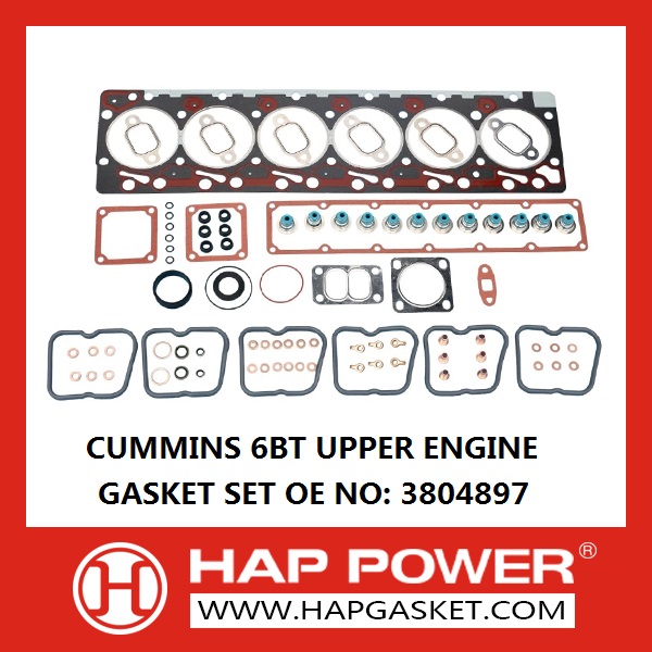
Cummins Sealing Products

Cummins is the world's largest independent engine manufacturer, including diesel and fuel engines, engine key components (fuel systems, control systems, intake air handling, filtration systems and tail gas treatment systems) and power generation systems.

HAP-CS-S-015  3804897 CUMMINS 6BT UPPER ENGINE GASKET SET


HAP produce most of the CUMMINS Head Gasket, Including following engines:

4B3.9

4BT 3.9

4BTA 3.9

6BT 5.9

6BTA 5.9

6C

6CT

6CT 8.3

6CT GRAPHITE

NT855

NH250

NT855 NEW

N-14

NH220

VT28

K SERIES

K19

KT19

K38

K50

ISBE4

ISBE6

6L

6LATT

L375

ISLE

ISCE

ISX

ISX15

S15

L10

M11

ISD 4

ISD 6

6BTEFI (Electric fule Injection)

ISF3.8

ISF2.8

- -.

Cummins Sealing Products,Cummins Head Gasket,Cummins Cylinder Head Gasket,Cummins Sealing Gaskts

NINGBO BEILUN QIANYI SEALING CO.,LTD. , https://www.hapgasket.com